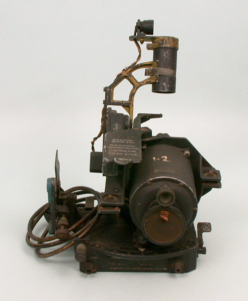
English: The "sighting head" from the RAF Mark XIVA bomb sight. This forms one half of the bombsight, attaching to the "computor", shown separately.
The large cylinder in the lower right houses the gyroscopic stabilization system. This was used to keep the entire platform flat in relation to the ground, providing a stable sighting platform. It was adapted from a Sperry artificial horizon, and its shape belies its original purpose in that it would normally fit into a hole on the pilot's instrument panel and screw in at the four corners of the front of the device, which is at the distant end in this view. One of the four screw points can be seen, on the upper right of the device.
The prominent arm extending from the top of the device holds the collimator (black cylinder) that projects an image of a cross-hair onto a mirror. The arm moves fore and aft to change the aiming angle, toward or away from the viewer as seen in this photograph. The angle is driven by the flexible cables, coiled up on the left. The sighting mirror is not present in this example, it would normally be fit into the C-shaped metal fitting below the collimator (only the upper part is visible, forming a black metal finger pointing to the right). The metal flap with writing on it, above and to the left of the gyro, rotates to the left and around so it would cover the mirror to protect it.
Along the bottom of the device, just visible (look for the white triangle), is a scale showing the drift angle, the difference between the heading and the direction of flight due to winds. During operation, the flexible cables would rotate the entire upper sight assembly to indicate the proper direction to fly in order to cancel out any sideways drift. The L-shaped flap on the extreme lower right could be pressed to unlock the sight from the driving cable, allowing it to be moved by hand. This was used to take drift measurements though the sight by reading off the scale.
The vertical assembly on the far left is used for levelling with respect to the computor, normally needed only after the computer or sight head had been moved. The entire assembly could be slid off the mounting arms that would sit to the left of this unit, and were interchangeable with several other sights.
Several parts are missing in this image. On the upper left of the collimator is a flower-pot shaped fitting that normally holds a small light bulb directly over the top of the collimator. The light bulb is missing, but the wires that fed power to it are visible. A housing fits around the bulb, so fully assembled the entire assembly looks like an upside-down "L" instead of the two separate parts seen here. The handle that allows manual movement of the collimator is also missing, it normally connects to the circular fitting visible at the bottom left of the arm, to the left of the metal flap. This was used to rotate the sight forward to take sights off of objects far in front of the bomber, normally in order to ensure the aircraft was approaching the target long before reaching it. When not in use, the handle was rotated forward to safely position the collimator assembly.


